Unit-1
Topologies
The arrangement of a network that comprises nodes and connecting lines via sender and receiver is referred to as network topology. The various network topologies are:
- Mesh Topology
- Star Topology
- Ring Topology
- Tree Topology
- Bus Topology
- Hybrid Topology
Mesh Topology:
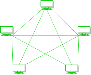
- In a mesh topology, every device is connected to another device via a particular channel.
- Every device is connected to another via dedicated channels. These channels are known as links.
Advantages of this topology:
- Communication is very fast between the nodes.
- It is robust.
- The fault is diagnosed easily. Data is reliable because data is transferred among the devices through dedicated channels or links.
- Provides security and privacy.
Disadvantages of this topology:
- Installation and configuration are difficult.
- The cost of cables is high as bulk wiring is required, hence suitable for less number of devices.
- The cost of maintenance is high.
- A common example of mesh topology is the internet backbone, where various internet service providers are connected to each other via dedicated channels.
- This topology is also used in military communication systems and aircraft navigation systems.
Star Topology:

- In star topology, all the devices are connected to a single hub through a cable.
- This hub is the central node and all other nodes are connected to the central node.
- The hub can be passive in nature i.e., not an intelligent hub such as broadcasting devices, at the same time the hub can be intelligent known as an active hub. Active hubs have repeaters in them.
- Coaxial cables or RJ-45 cables are used to connect the computers.
Advantages of this topology:
- If N devices are connected to each other in a star topology, then the number of cables required to connect them is N. So, it is easy to set up.
- Each device requires only 1 port i.e. to connect to the hub, therefore the total number of ports required is N.
- It is Robust. If one link fails only that link will affect and not other than that.
Disadvantages of this topology:
- If the concentrator (hub) on which the whole topology relies fails, the whole system will crash down.
- The cost of installation is high.
- Performance is based on the single concentrator i.e. hub.
- A common example of star topology is a local area network (LAN) in an office where all computers are connected to a central hub.
- This topology is also used in wireless networks where all devices are connected to a wireless access point.
Bus Topology:
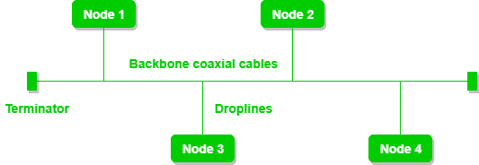
- Bus topology is a network type in which every computer and network device is connected to a single cable.
- It is bi-directional.
- It is a multi-point connection and a non-robust topology because if the backbone fails the topology crashes.
Advantages of this topology:
- If N devices are connected to each other in a bus topology, then the number of cables required to connect them is 1, known as backbone cable, and N drop lines are required.
- Coaxial or twisted pair cables are mainly used in bus-based networks that support up to 10 Mbps.
- The cost of the cable is less compared to other topologies, but it is used to build small networks.
- Bus topology is familiar technology as installation and troubleshooting techniques are well known.
Disadvantages of this topology:
- A bus topology is quite simpler, but still, it requires a lot of cabling.
- If the common cable fails, then the whole system will crash down.
- If the network traffic is heavy, it increases collisions in the network. To avoid this, various protocols are used in the MAC layer known as Pure Aloha, Slotted Aloha, CSMA/CD, etc.
- Adding new devices to the network would slow down networks.
- Security is very low.
- A common example of bus topology is the Ethernet LAN, where all devices are connected to a single coaxial cable or twisted pair cable.
- This topology is also used in cable television networks.
Ring Topology:
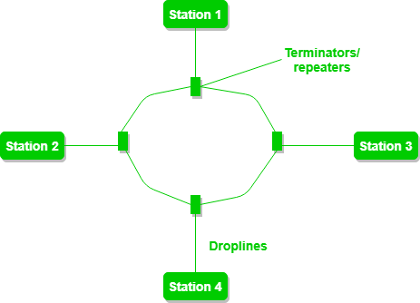
- In this topology, it forms a ring connecting devices with exactly two neighboring devices.
- A number of repeaters are used for Ring topology with a large number of nodes, because if someone wants to send some data to the last node in the ring topology with 100 nodes, then the data will have to pass through 99 nodes to reach the 100th node. Hence to prevent data loss repeaters are used in the network.
- The data flows in one direction, i.e.., it is unidirectional, but it can be made bidirectional by having 2 connections between each Network Node, it is called Dual Ring Topology.
- In-Ring Topology, the Token Ring Passing protocol is used by the workstations to transmit the data.
- A ring topology comprises 4 stations connected with each forming a ring.
Advantages of this topology:
- The data transmission is high-speed.
- The possibility of collision is minimum in this type of topology.
- Cheap to install and expand.
- It is less costly than a star topology.
Disadvantages of this topology:
- The failure of a single node in the network can cause the entire network to fail.
- Troubleshooting is difficult in this topology.
- The addition of stations in between or the removal of stations can disturb the whole topology.
- Less secure.
- A common example of bus topology is the Ethernet LAN, where all devices are connected to a single coaxial cable or twisted pair cable.
- This topology is also used in cable television networks.
Tree Topology :

- This topology is the variation of the Star topology.
- This topology has a hierarchical flow of data.
- In Tree Topology, protocols like DHCP and SAC (Standard Automatic Configuration ) are used.
- In this, the various secondary hubs are connected to the central hub which contains the repeater.
- This data flow from top to bottom i.e. from the central hub to the secondary and then to the devices or from bottom to top i.e. devices to the secondary hub and then to the central hub.
- It is a multi-point connection and a non-robust topology because if the backbone fails the topology crashes.
Advantages of this topology :
- It allows more devices to be attached to a single central hub thus it decreases the distance that is traveled by the signal to come to the devices.
- It allows the network to get isolated and also prioritize from different computers.
- We can add new devices to the existing network.
- Error detection and error correction are very easy in a tree topology.
Disadvantages of this topology :
- If the central hub gets fails the entire system fails.
- The cost is high because of the cabling.
- If new devices are added, it becomes difficult to reconfigure.
- A common example of a tree topology is the hierarchy in a large organization.
- At the top of the tree is the CEO, who is connected to the different departments or divisions (child nodes) of the company.
- Each department has its own hierarchy, with managers overseeing different teams (grandchild nodes).
- The team members (leaf nodes) are at the bottom of the hierarchy, connected to their respective managers and departments.
Hybrid Topology :

- This topological technology is the combination of all the various types of topologies .
- It is used when the nodes are free to take any form.
- It means these can be individuals such as Ring or Star topology or can be a combination of various types of topologies .
Advantages of this topology :
- This topology is very flexible.
- The size of the network can be easily expanded by adding new devices.
Disadvantages ofthis topology :
- It is challenging to design the architecture of the Hybrid Network.
- Hubs used in this topology are very expensive.
- The infrastructure cost is very high as a hybrid network requires a lot of cabling and network devices.
- A common example of a hybrid topology is a university campus network.
- The failure of a single node in the network can cause the entire network to fail.
- Troubleshooting is difficult in this topology.
- The addition of stations in between or the removal of stations can disturb the whole topology.
- Less secure.
- A common example of bus topology is the Ethernet LAN, where all devices are connected to a single coaxial cable or twisted pair cable.
- This topology is also used in cable television networks.
Tree Topology :
- This topology is the variation of the Star topology.
- This topology has a hierarchical flow of data.
- In Tree Topology, protocols like DHCP and SAC (Standard Automatic Configuration ) are used.
- In this, the various secondary hubs are connected to the central hub which contains the repeater.
- This data flow from top to bottom i.e. from the central hub to the secondary and then to the devices or from bottom to top i.e. devices to the secondary hub and then to the central hub.
- It is a multi-point connection and a non-robust topology because if the backbone fails the topology crashes.
Advantages of this topology :
- It allows more devices to be attached to a single central hub thus it decreases the distance that is traveled by the signal to come to the devices.
- It allows the network to get isolated and also prioritize from different computers.
- We can add new devices to the existing network.
- Error detection and error correction are very easy in a tree topology.
Disadvantages of this topology :
- If the central hub gets fails the entire system fails.
- The cost is high because of the cabling.
- If new devices are added, it becomes difficult to reconfigure.
- A common example of a tree topology is the hierarchy in a large organization.
- At the top of the tree is the CEO, who is connected to the different departments or divisions (child nodes) of the company.
- Each department has its own hierarchy, with managers overseeing different teams (grandchild nodes).
- The team members (leaf nodes) are at the bottom of the hierarchy, connected to their respective managers and departments.
Hybrid Topology :
- This topological technology is the combination of all the various types of topologies .
- It is used when the nodes are free to take any form.
- It means these can be individuals such as Ring or Star topology or can be a combination of various types of topologies .
Advantages of this topology :
- This topology is very flexible.
- The size of the network can be easily expanded by adding new devices.
Disadvantages ofthis topology :
- It is challenging to design the architecture of the Hybrid Network.
- Hubs used in this topology are very expensive.
- The infrastructure cost is very high as a hybrid network requires a lot of cabling and network devices.
- A common example of a hybrid topology is a university campus network.
- It allows more devices to be attached to a single central hub thus it decreases the distance that is traveled by the signal to come to the devices.
- It allows the network to get isolated and also prioritize from different computers.
- We can add new devices to the existing network.
- Error detection and error correction are very easy in a tree topology.
Disadvantages of this topology :
- If the central hub gets fails the entire system fails.
- The cost is high because of the cabling.
- If new devices are added, it becomes difficult to reconfigure.
- A common example of a tree topology is the hierarchy in a large organization.
- At the top of the tree is the CEO, who is connected to the different departments or divisions (child nodes) of the company.
- Each department has its own hierarchy, with managers overseeing different teams (grandchild nodes).
- The team members (leaf nodes) are at the bottom of the hierarchy, connected to their respective managers and departments.
Hybrid Topology :
- This topological technology is the combination of all the various types of topologies .
- It is used when the nodes are free to take any form.
- It means these can be individuals such as Ring or Star topology or can be a combination of various types of topologies .
Advantages of this topology :
- This topology is very flexible.
- The size of the network can be easily expanded by adding new devices.
- It is challenging to design the architecture of the Hybrid Network.
- Hubs used in this topology are very expensive.
- The infrastructure cost is very high as a hybrid network requires a lot of cabling and network devices.
- A common example of a hybrid topology is a university campus network.
Disadvantages ofthis topology :
Data Communication Components
- Data Communication is defined as exchange of data between two devices via some form of transmission media such as a cable, wire or it can be air or vacuum also.
- For occurrence of data communication, communicating devices must be a part of communication system made up of a combination of hardware or software devices and programs.
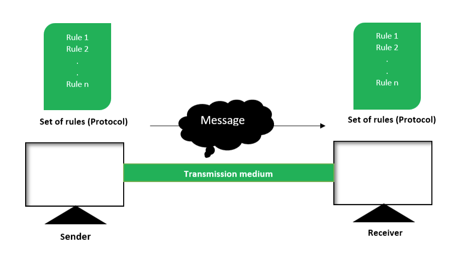
There are mainly five components of a data communication system:
- Message
- Sender
- Receiver
- Transmission Medium
- Set of rules (Protocol)
All above mentioned elements are described below:
Message :
Sender :
Receiver :
Transmission Medium :
Set of rules (Protocol) :
A typical example of a data communication system is sending an e-mail.
The user which send email act as sender,
message is data which user wants to send,
receiver is one whom user wants to send message,
there are many protocols involved in this entire process,
one of them is Simple Mail Transfer Protocol (SMTP),
both sender and receiver must have an internet connection which uses a wireless medium to send and receive email.
Types of Networks
A computer network is a cluster of computers over a shared communication path that works for the purpose of sharing resources from one computer to another, provided by or located on the network nodes. Some of the uses of computer networks are the following:
- Communicating using email, video, instant messaging, etc.
- Sharing devices such as printers, scanners, etc.
- Sharing files
- Sharing software and operating programs on remote systems
- Allowing network users to easily access and maintain information
Types of Computer Networks
- Personal Area Network (PAN)
- Local Area Network (LAN)
- Wide Area Network (WAN)
- Wireless Local Area Network (WLAN)
- Campus Area Network (CAN)
- Metropolitan Area Network (MAN)
- System-Area Network (SAN)
These are explained as following below.
Personal Area Network (PAN) :
- PAN is the most basic type of computer network.
- This network is restrained to a single person, that is, communication between the computer devices is centered only to an individual’s workspace.
- PAN offers a network range of 1 to 100 meters from person to device providing communication.
- Its transmission speed is very high with very easy maintenance and very low cost.
- This uses BlueTooth, IrDA, and Zigbee as technology.
- Examples of PAN are USB, computer, phone, tablet, printer, PDA, etc.
Local Area Network (LAN) :
- LAN is the most frequently used network.
- A LAN is a computer network that connects computers together through a common communication path, contained within a limited area, that is, locally.
- A LAN encompasses two or more computers connected over a server.
- The two important technologies involved in this network are Ethernet and Wi-fi.
- It ranges up to 2km & transmission speed is very high with easy maintenance and low cost.
- Examples of LAN are networking in a home, school, library, laboratory, college, office, etc.
Wide Area Network (WAN) :
- WAN is a type of computer network that connects computers over a large geographical distance through a shared communication path.
- It is not restrained to a single location but extends over many locations.
- WAN can also be defined as a group of local area networks that communicate with each other with a range above 50km.
- Here we use Leased-Line & Dial-up technology.
- Its transmission speed is very low and it comes with very high maintenance and very high cost.
- The most common example of WAN is the Internet.
Wireless Local Area Network (WLAN) :
- WLAN is a type of computer network that acts as a local area network but makes use of wireless network technology like Wi-Fi.
- This network doesn’t allow devices to communicate over physical cables like in LAN but allows devices to communicate wirelessly.
- The most common example of WLAN is Wi-Fi.
Campus Area Network (CAN) :
- CAN is bigger than a LAN but smaller than a MAN.
- This is a type of computer network that is usually used in places like a school or colleges.
- This network covers a limited geographical area that is, it spreads across several buildings within the campus.
- CAN mainly use Ethernet technology with a range from 1km to 5km.
- Its transmission speed is very high with a moderate maintenance cost and moderate cost.
- Examples of CAN are networks that cover schools, colleges, buildings, etc.
Metropolitan Area Network (MAN) :
- A MAN is larger than a LAN but smaller than a WAN.
- This is the type of computer network that connects computers over a geographical distance through a shared communication path over a city, town, or metropolitan area.
- This network mainly uses FDDI, CDDI, and ATM as the technology with a range from 5km to 50km.
- Its transmission speed is average. It is difficult to maintain and it comes with high cost.
- Examples of MAN are networking in towns, cities, a single large city, a large area within multiple buildings, etc.
Storage Area Network (SAN) :
- SAN is a type of computer network that is high-speed and connects groups of storage devices to several servers.
- This network does not depend on LAN or WAN.
- Instead, a SAN moves the storage resources from the network to its own high-powered network.
- A SAN provides access to block-level data storage.
- Examples of SAN are a network of disks accessed by a network of servers.
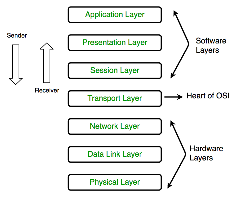
OSI Model
- The Open Systems Interconnection (OSI) Model was developed by International Organization for Standardization (ISO).
- ISO is the organization, OSI is the model.
- It was developed to allow systems with different platforms to communicate with each other.
- Platform could mean hardware, software or operating system.
- It is a network model that defines the protocols for network communications.
- It is a hierarchical model that groups its processes into layers.
- Each layer has specific duties to perform and has to cooperate with the layers above and below it.
- It has 7 layers as follows: (Top to Bottom)
- Application Layer
- Presentation Layer
- Session Layer
- Transport Layer
- Network Layer
- Data Link Layer
- Physical Layer
Functions of the Layers
Physical Layer :
Data Link Layer :
Network Layer :
Transport Layer :
Session Layer :
Presentation Layer :
Application Layer :
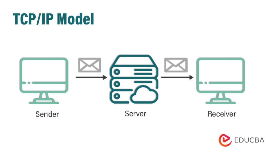
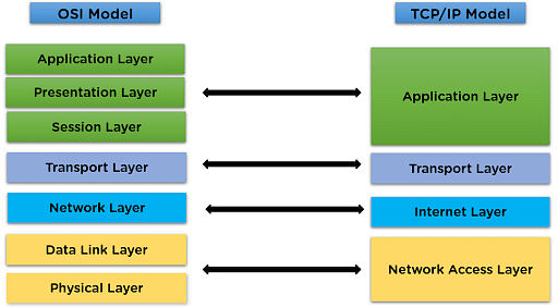
TCP/IP
- Application Layer
- Transport Layer(TCP/UDP)
- Network/Internet Layer(IP)
- Data Link Layer (MAC)
- Physical Layer
Physical Layer:
Data Link Layer:
Internet Layer:
Transport Layer:
Application Layer:
Transmission Media
i.e. it is the channel through which data is sent from one place to another.
Guided Media:
It is also referred to as Wired or Bounded transmission media.- High Speed
- Secure
- Used for comparatively shorter distances
- Twisted Pair Cable
- It consists of 2 separately insulated conductor wires wound about each other.
- Generally, several such pairs are bundled together in a protective sheath.
- They are the most widely used Transmission Media.
- Twisted Pair is of two types:
- UTP consists of two insulated copper wires twisted around one another.
- This type of cable has the ability to block interference and does not depend on a physical shield for this purpose.
- It is used for telephonic applications.
- Least expensive
- Easy to install
- High-speed capacity Disadvantages:
- Susceptible to external interference
- Lower capacity and performance in comparison to STP
- Short distance transmission due to attenuation
- Used in telephone connections and LAN networks
- This type of cable consists of a special jacket (a copper braid covering or a foil shield) to block external interference.
- It is used in fast-data-rate Ethernet and in voice and data channels of telephone lines.
- Better performance at a higher data rate in comparison to UTP
- Eliminates crosstalk
- Comparatively faster
- Comparatively difficult to install and manufacture
- More expensive
- Bulky
- The shielded twisted pair type of cable is most frequently used in extremely cold climates,
where the additional layer of outer covering makes it perfect for withstanding such temperatures or for shielding the interior components. - It has an outer plastic covering containing an insulation layer made of PVC or Teflon and 2 parallel conductors each having a separate insulated protection cover.
- The coaxial cable transmits information in two modes: Baseband mode(dedicated cable bandwidth) and Broadband mode(cable bandwidth is split into separate ranges).
- Cable TVs and analog television networks widely use Coaxial cables.
- High Bandwidth
- Better noise Immunity
- Easy to install and expand
- Inexpensive
- Single cable failure can disrupt the entire network
- Radio frequency signals are sent over coaxial wire.
- It can be used for cable television signal distribution, digital audio (S/PDIF), computer network connections (like Ethernet),
and feedlines that connect radio transmitters and receivers to their antennas. - It uses the concept of refraction of light through a core made up of glass or plastic.
- The core is surrounded by a less dense glass or plastic covering called the cladding.
- It is used for the transmission of large volumes of data.
- Increased capacity and bandwidth
- Lightweight
- Less signal attenuation
- Immunity to electromagnetic interference
- Resistance to corrosive materials
- Difficult to install and maintain
- High cost
- Fragile
- Medical Purpose: Used in several types of medical instruments.
- Defence Purpose: Used in transmission of data in aerospace.
- For Communication: This is largely used in formation of internet cables.
- Industrial Purpose: Used for lighting purposes and safety measures in designing the interior and exterior of automobiles.
Unguided Media:
- It is also referred to as Wireless or Unbounded transmission media.
- No physical medium is required for the transmission of electromagnetic signals.
- The signal is broadcasted through air
- Less Secure
- Used for larger distances
- There are 3 types of Signals transmitted through unguided media:
- Radio waves
- These are easy to generate and can penetrate through buildings.
- The sending and receiving antennas need not be aligned. Frequency Range:3KHz to 1GHz.
- AM and FM radios and cordless phones use Radio waves for transmission.
- Microwaves
- It is a line of sight transmission i.e. the sending and receiving antennas need to be properly aligned with each other.
- The distance covered by the signal is directly proportional to the height of the antenna.
- Frequency Range:1GHz to 300GHz.
- These are majorly used for mobile phone communication and television distribution.
- Infrared
- Infrared waves are used for very short distance communication.
- They cannot penetrate through obstacles.
- This prevents interference between systems.
- Frequency Range:300GHz to 400THz.
- It is used in TV remotes, wireless mouse, keyboard, printer, etc.
Signals being transmitted are directed and confined in a narrow pathway by using physical links.
Features:There are 3 major types of Guided Media:
Further Categorized as
1. Terrestrial
2.Satellite.
Unit-2
Multiplexing
Types of Multiplexing
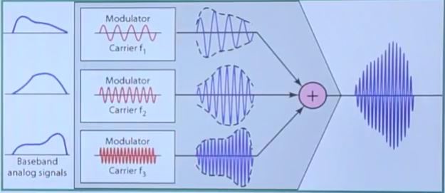
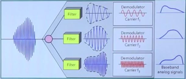
1. Frequency Division Multiplexing (FDM)
2. Time-Division Multiplexing (TDM)
1. Frequency Division Multiplexing :

independent frequency channels.
Application of FDM:
(i) In the first generation of mobile phones, FDM was used.
(ii) The use of FDM in television broadcasting
(iii) FDM is used to broadcast FM and AM radio frequencies.
2. Time Division Multiplexing :
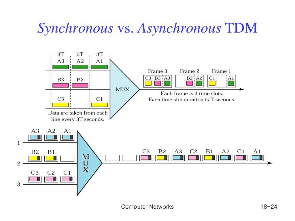
There are two types of Time Division Multiplexing :
i. Synchronous Time Division Multiplexing
ii. Statistical (or Asynchronous) Time Division Multiplexing
Sliding window Protocol
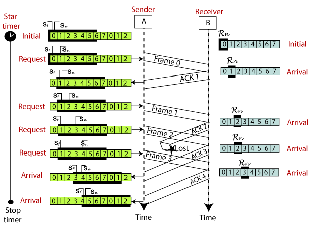
For example, if the sending window size is 4,
then the
sequence numbers will be 0, 1, 2, 3, 0, 1, 2, 3, 0, 1, and so on.
The number of bits in the sequence number
is 2 to generate the binary sequence 00, 01, 10, 11.
The size of the receiving window is the maximum number of frames that the receiver can accept at a time.
It determines the maximum number of frames that the sender can send before receiving acknowledgment.
Example
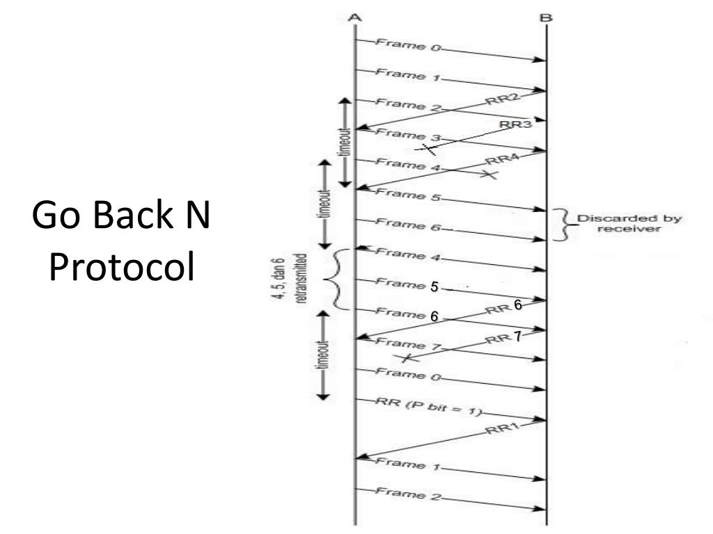
Go Back-N ARQ
Selective Repeat ARQ

Hamming Code
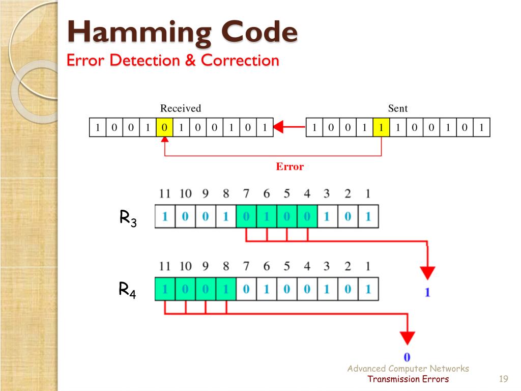
The procedure used by the sender to encode the message encompasses the following steps
Step 1 - Calculation of the number of redundant bits.
Step 2 - Positioning the redundant bits.
Step 3 - Calculating the values of each redundant bit.
Decoding a message in Hamming Code
Once the receiver gets an incoming message, it performs recalculations to detect errors and correct them.
The steps for recalculation are
Step 1 - Calculation of the number of redundant bits.
Step 2 - Positioning the redundant bits.
Step 3 - Parity checking.
Step 4 - Error detection and correction
Error Detection Techniques
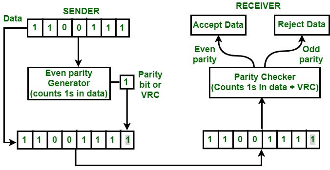
1. Simple Parity check
2. Two-dimensional Parity check
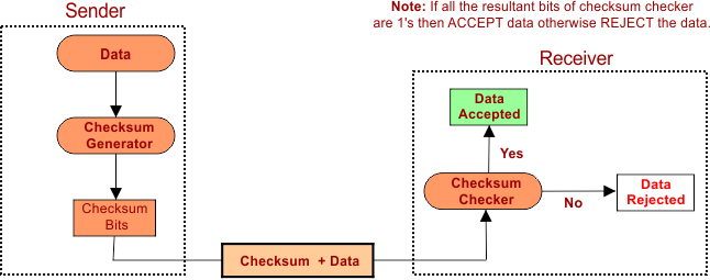
3. Checksum
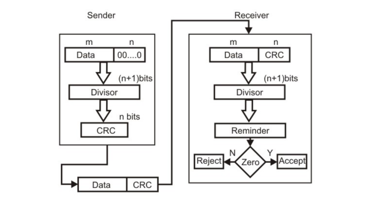
4. Cyclic redundancy check
Simple Parity check
Two-dimensional Parity check

Checksum
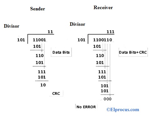
Cyclic redundancy check (CRC)
Data Link Controls
o Line discipline
o Flow Control
o Error Control
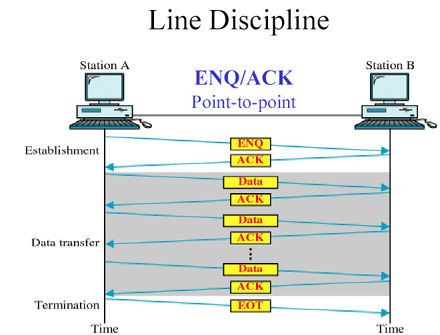
Line Discipline
- ENQ/ACK
- Poll/select
* Enquiry/Acknowledgement (ENQ/ACK) :
* Poll/ Select :
- Polling :
- Selecting :
When primary device wants to receive details asks secondary devices if they have anything to send,
this
function is called polling.
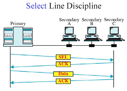
When primary device wants to send data to any secondary device,
it tells that device to be ready to
receive data, this function is called selecting.
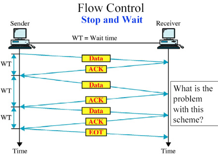
Flow Control :
Example: Stop & Wait Protocol
Error Control :

and the acknowledgement frames that are lost in transmission.
Example :Stop & Wait ARQ and Sliding Window ARQStop and Wait Protocol
What is Stop and Wait protocol?
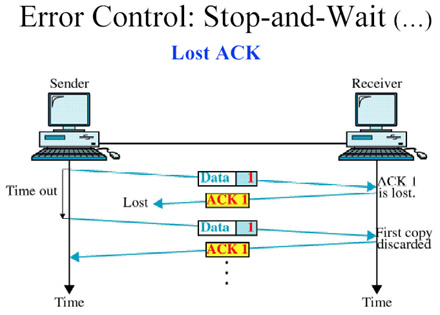
Sender side
Rule 1: Sender sends one data packet at a time.
Rule 2: Sender sends the next packet only when it receives the acknowledgment of the previous packet.
Therefore, the idea of stop and wait protocol in the sender's side is very simple, i.e.,
send one packet at a
time, and do not send another packet before receiving the acknowledgment.
Receiver side
Rule 1: Receive and then consume the data packet.
Rule 2: When the data packet is consumed, receiver sends the acknowledgment to the sender.
Therefore, the idea of stop and wait protocol in the receiver's side is also very simple,
i.e., consume the
packet, and once the packet is consumed,
the acknowledgment is sent. This is known as a flow control
mechanism.
Unit-3
IEEE 802
i. IEEE 802.3
ii.IEEE 802.3a
iii.IEEE 802.3
Token Passing Mechanism in Token Ring
Token Passing Mechanism in Token Bus
CSMA
CSMA CD
There are mainly two conditions for the carrier, which are as follows
i. Carrier is busy transmission take place
ii.Carrier is idle -no transmission takes place.
Advantages of CSMA CD:
Disadvantage of CSMA CD
CSMA/CA
- When a frame is ready, the transmitting station checks whether the channel is idle or busy.
- If the channel is busy, the station waits until the channel becomes idle.
- If the channel is idle, the station starts transmitting and continually monitors the channel to detect collision.
- If a collision is detected, the station starts the collision resolution algorithm.
- The station resets the retransmission counters and completes frame transmission.
The algorithm of Collision Resolution is:
- The station continues transmission of the current frame for a specified time along with a jam signal, to ensure that all the other stations detect collision.
- The station increments the retransmission counter.
- If the maximum number of retransmission attempts is reached, then the station aborts transmission.
- Otherwise, the station waits for a backoff period which is generally a function of the number of collisions and restart main algorithm.
- Though this algorithm detects collisions, it does not reduce the number of collisions.
- It is not appropriate for large networks performance degrades exponentially when more stations are added.
- When the size of data packets is large, the chances of collision in CSMA CA is less.
- It controls the data packets and sends the data when the receiver wants to send them.
- It is used to prevent collision rather than collision detection on the shared channel.
- CSMA CA avoids wasted transmission of data over the channel.
- It is best suited for wireless transmission in a network.
- It avoids unnecessary data traffic on the network with the help of the RTS/ CTS extension.
- Sometime CSMA/CA takes much waiting time as usual to transmit the data packet.
- It consumes more bandwidth by each station.
- Its efficiency is less than a CSMA CD.
Advantage of CSMA CA
Disadvantage of CSMA CA
Switching Methods
- In large networks, there can be multiple paths from sender to receiver.
- The switching technique will decide the best route for data transmission.
- Switching technique is used to connect the systems for making one-to-one communication.
Circuit Switching
- Circuit switching is a switching technique that establishes a dedicated path between sender and receiver.
- In the Circuit Switching Technique, once the connection is established then the dedicated path will remain to exist until the connection is terminated.
- Circuit switching in a network operates in a similar way as the telephone works.
- A complete end-to-end path must exist before the communication takes place.
- In case of circuit switching technique, when any user wants to send the data, voice, video, a request signal is sent to the receiver then the receiver sends back the acknowledgment to ensure the availability of the dedicated path.
- After receiving the acknowledgment, dedicated path transfers the data.
- Circuit switching is used in public telephone network. It is used for voice transmission.
Advantages Of Circuit Switching:
- In the case of Circuit Switching technique, the communication channel is dedicated.
- It has fixed bandwidth.
Disadvantages Of Circuit Switching:
- Once the dedicated path is established, the only delay occurs in the speed of data transmission.
- It takes a long time to establish a connection approx 10 seconds during which no data can be transmitted.
- It is more expensive than other switching techniques as a dedicated path is required for each connection.
- It is inefficient to use because once the path is established and no data is transferred, then the capacity of the path is wasted.
- In this case, the connection is dedicated therefore no other data can be transferred even if the channel is free.
Message Switching
- Message Switching is a switching technique in which a message is transferred as a complete unit and routed through intermediate nodes at which it is stored and forwarded.
- In Message Switching technique, there is no establishment of a dedicated path between the sender and receiver.
- The destination address is appended to the message. Message Switching provides a dynamic routing as the message is routed through the intermediate nodes based on the information available in the message.
- Message switches are programmed in such a way so that they can provide the most efficient routes.
- Each and every node stores the entire message and then forward it to the next node.
- This type of network is known as store and forward network.
- Message switching treats each message as an independent entity.
Advantages Of Message Switching
- Data channels are shared among the communicating devices that improve the efficiency of using available bandwidth.
- Traffic congestion can be reduced because the message is temporarily stored in the nodes.
- Message priority can be used to manage the network.
- The size of the message which is sent over the network can be varied. Therefore, it supports the data of unlimited size.
Disadvantages Of Message Switching
- The message switches must be equipped with sufficient storage to enable them to store the messages until the message is forwarded.
- The Long delay can occur due to the storing and forwarding facility provided by the message switching technique.
Packet Switching
- The packet switching is a switching technique in which the message is sent in one go, but it is divided into smaller pieces, and they are sent individually.
- The message splits into smaller pieces known as packets and packets are given a unique number to identify their order at the receiving end.
- Every packet contains some information in its headers such as source address, destination address and sequence number.
- Packets will travel across the network, taking the shortest path as possible.
- All the packets are reassembled at the receiving end in correct order.
- If any packet is missing or corrupted, then the message will be sent to resend the message.
- If the correct order of the packets is reached, then the acknowledgment message will be sent.
Advantages Of Packet Switching:
- Cost-effective
- Reliable
- Efficient
Disadvantages Of Packet Switching:
- Packet Switching technique cannot be implemented in those applications that require low delay and high-quality services.
- The protocols used in a packet switching technique are very complex and requires high implementation cost.
- If the network is overloaded or corrupted, then it requires retransmission of lost packets.
- It can also lead to the loss of critical information if errors are nor recovered.
Unit-4
Networking Devices & Internetworking Devices
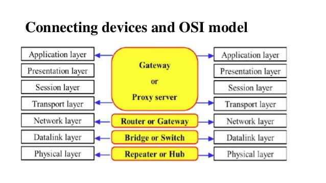
Networking devices
Repeaters
Advantages of Repeaters
Disadvantages of Repeaters
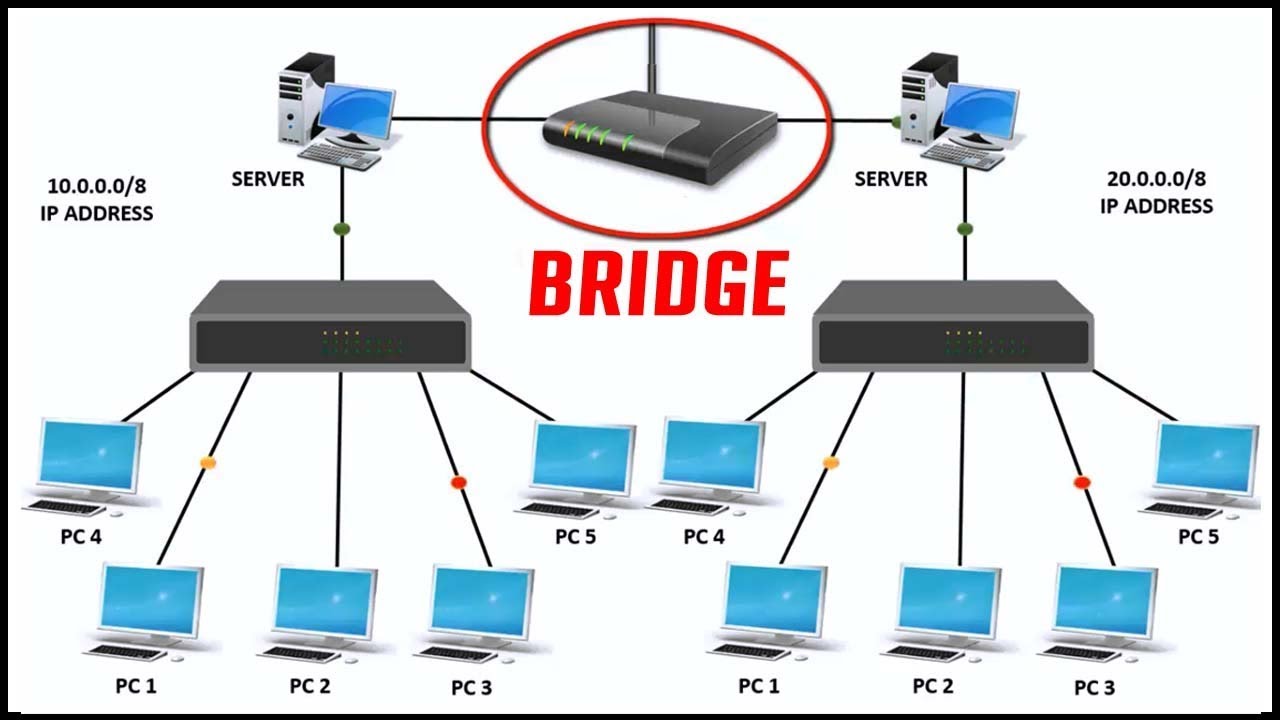
Bridges
Internetworking Devices
Gateways

Routers
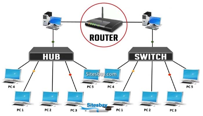
Types of Routers
- Wireless Router
- They provide WiFi connection WiFi devices like laptops, smartphones etc.
- They can also provide standard Ethernet routing.
- For indoor connections, the range is 150 feet while its 300 feet for outdoor connections.
- Broadband Router
- They are used to connect to the Internet through telephone and to use voice over Internet Protocol (VoIP) technology for providing high-speed Internet access.
- They are configured and provided by the Internet Service Provider (ISP).
- Core Routers
- They can route data packets within a given network, but cannot route the packets between the networks.
- They helps to link all devices within a network thus forming the backbone of network.
- It is used by ISP and communication interfaces.
- Edge Routers
- They are low-capacity routers placed at the periphery of the networks.
- They connect the internal network to the external networks, and are suitable for transferring data packets across networks.
- They use Border Gateway Protocol (BGP) for connectivity.
- Brouters
- Brouters are specialised routers that can provide the functionalities of bridges as well.
- Like a bridge, brouters help to transfer data between networks.
- And like a router, they route the data within the devices of a network.
Transport Layer

Responsibilities of a Transport Layer:
Process to process delivery:of source-destination hosts to correctly deliver a frame and the Network layer requires the IP address for appropriate routing of packets,
in a similar way Transport Layer requires a Port number to correctly deliver the segments of data to the correct process amongst the multiple processes running on a particular host.
it checks whether the received data is not corrupted and uses the ACK and NACK services to inform the sender if the data has arrived or not and checks for the integrity of data.
Session Layer
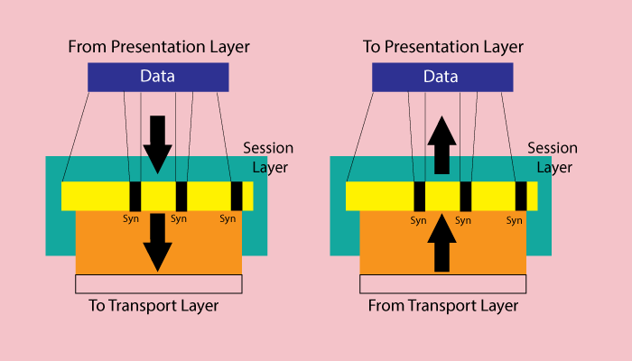
- User abort
- Provider abort
- Orderly release
- Negotiated release
Application Layer
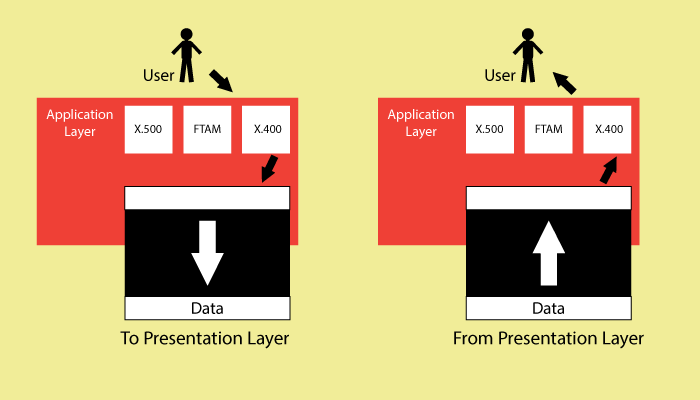
The Application layer includes the following functions:
Presentation Layer
